Sunday, May 22, 2011

Modifications to Construction

When I unpacked the kit, the panels seemed very thin, I was surprised that 6 mm was enough. It was hard to put it into perspective unpacking the box, I was thinking oh oh, I spent a lot of money for a toy that will be broken in a season. I can assure you the PMD is no toy. Once you put the seats on you will understand, it really becomes a boat then. Think about a aluminum row boat, they can really take a beating, how thick is the hull? Enough said.

Writing this blog in reverse has its advantages, Today, after the fog lifts I intend to go sailing on Lake Michigan, it is predicted to be 1-2 foot waves with a south wind at 10-15 knots with 20 knot gusts. The PMD can handle this with no trouble. I did however make a few modifications in both construction and rigging. In this post I will cover the modifications to the boat itself.

I added a 12X18 hatch and storage box instead of a deck plate. It has a water resistant seal and the storage  box is removable. I think it is water proof but the manufacturer plays it safe with the wording. I will not repeat what has been written in other PMD blogs about installing this. It is straightforward yet care must be taken to measure correctly. I am building a take apart version. When you cut the boat in half you will remove material, changing the measurements for the mast stop plate in relation to the hatch. When you add the gasket you will add distance, in the end it is a wash.


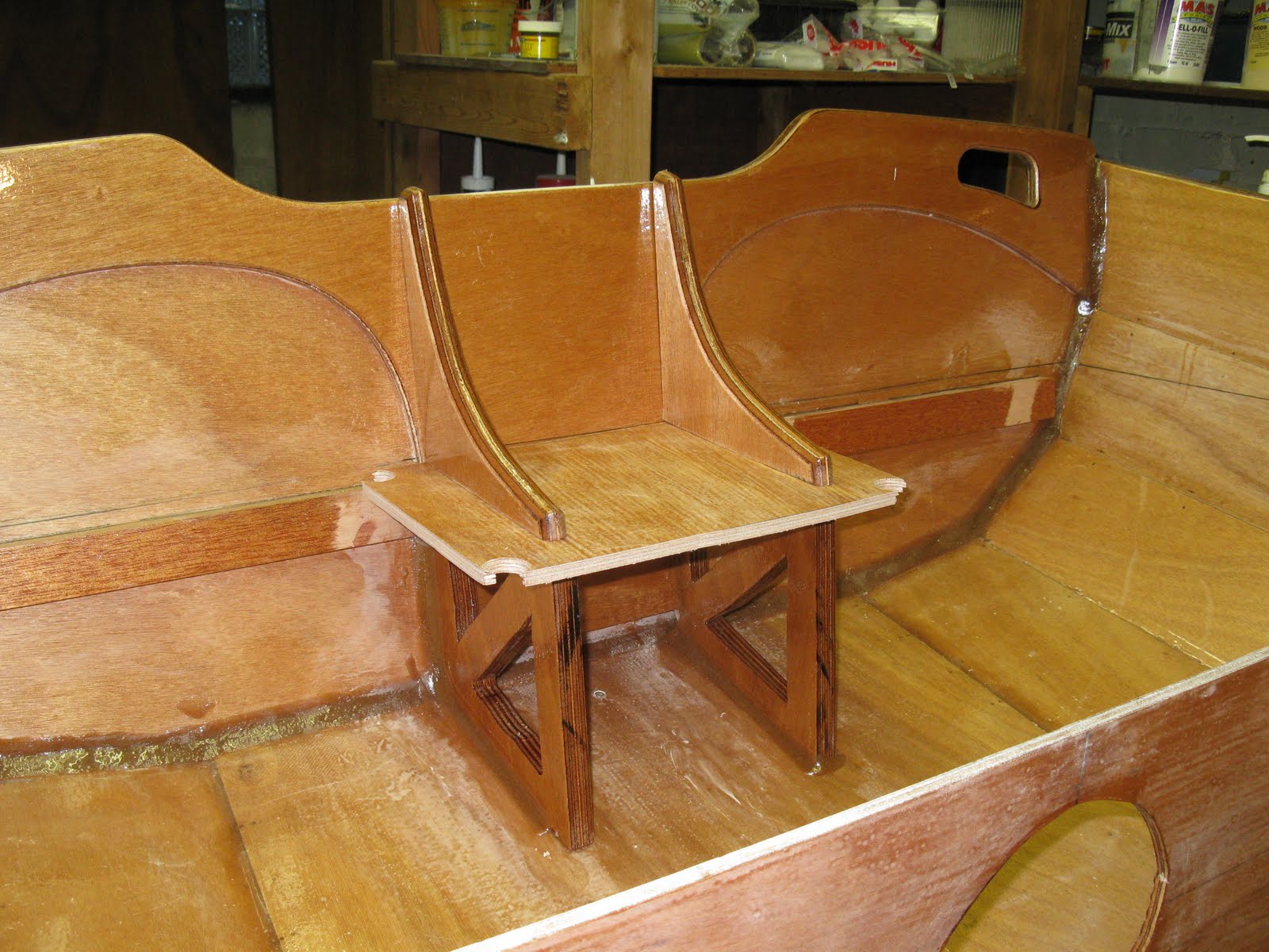
Below, I reinforced the deck for strength and to be able to use a 1" screw size.


Below the shot shows the 18mm mast support with a notch cut out to receive the mahogany deck support. This firmed up the deck and added compression support from top to bottom. Dry fittings are important to get it just right before you epoxy it all together. I would have liked to add a support on the hull to receive the deck supports but at this point, I was not confident where the deck will end up on the hull. As it turned out, locating the deck and gluing it on was a bit of a challenge. I needed to use the trick in the CLC manual with a clamp and stick to hold the deck close the the hull to get it epoxied in place. Great idea CLC!


My next modification was due to my new outboard. Thanks to Al Gore and all his tree hugging friends, two cycle engines are gone, four cycles suck! My engine weighs 55 lbs yet is only 4 hp. A two cycle that weighs 55 lbs would probably be a 10 hp. I really would like to find a 2 or 3 hp used two cycle, perfect for the PMD.

I read in the PMD forum about the guy that damaged his PMD by slamming it into gear at full power, so with a 55lb motor, I decided to beef up the transom a bit. I decided to use two knees instead of one. I also noticed in his pictures that his plywood failed as only the top layer was holding everything together. The weak link is the plywood. In reality, the epoxy in all the fillets sticks to the epoxy of the deck surface and that sticks to the plywood.
I made up two supports to go under the knees just below the deck. I added a compression plate to support the motor all the way down to the bottom panel and ended up with a three sided box. Here is how it looks.


At this point, I drilled a pilot hole thru the knee and deck and into the support. Once I assembled the seat, I  added a lag bolt to pass any load to the entire structure rather than rely on the plywood veneer glue to hold my motor on. I did the same thing at the top of the knee drilling into the motor plate.

I changed out the motor plate and used 18mm there too. Using a support box under the seat ended up being a really solid modification and supports the engine weight well. If I had not already spent $1600 on the engine for my zodiac, I would have used a smaller, lighter engine. With only 90lbs of displacement, and VC17, the PMD goes twice as fast at clutch speed than my zodiac did!

This boat moves so easy through the water, if you fart, you speed up! So far, I have only been at speeds just above idle and already I am past the harbor speed limit with NO wake at all. Nice! It will be interesting to get out into the lake and see how it handles more hp. I am not too sure if it will plane yet but I will let you know. Your weight really effects this boat. I find that I will need a tiller extension for the motor. With only one person, you have to be in the center seat. With two people, you can sit fore and aft just fine.

I put the cutout from the deck hatch in between temporarily so you can see how it works and as my dry fit. I also added a mahogany brace to help support the seat on the transom.


Saturday, May 21, 2011

The Dagger Board Box Debacle

When I built the center seat assembly, I used 6 clamps to assemble the dagger board box as shown in a picture in the PMD manual. The problem was that the plywood had a warp in both the side pieces. This sometimes is the case even in high quality plywood like Okoume. Humidity can be a factor in warping. I knew I had a warp, but I could hold the box assembly in a correct position with a little pressure. I figured the clamps would be about to hold the wood in a correct position and the epoxy would freeze the assembly in the correct position.

Note: Part of being a good carpenter is overcoming flaws in wood. Wood is natural and warps, bows twists and all mamner of deformations. I once watched a very expensive piece of solid mahogany twist and bow badly after it was cut to shape. The saw released some pressure in the grain and it was amazing to actually see it twist.

You can see the mast support in the right of the picture. Actually, It is not the one that came with the kit. I had a 4X8 sheet of 18 mm Okoume left over from replacing the rear bulkhead and deck house wall of my Chris Craft, so I used 18 mm for several pieces including the mast support, rudder, dagger board and a motor support structure that I will show you in a later post. It was not necessary, but as I had the material, I liked the idea of more substantial parts in load bearing places.

There were slight warps in the 12 mm rudder and dagger board parts in the kit. I did not want the rudder and dagger board "fighting" each other while sailing. Obsessive, I know but I am even using VC17 on the bottom for speed as well as the fact that I leave the dinghy in the water all season. I may even try some dinghy racing so speed could be a factor.

In the end, I though the clamps were sufficient and it looked OK when I applied the expoy. I was wrong, the clamps I used were too weak to hold the warp in the correct position . When I came down the next day, I found the assembly was warped in two directions. It was not too bad and I convinced myself it would be OK once I glued it down on to the rest of the seat assembly. I was in a hurry to get going and had my rose colored glasses on that day. So, I went ahead and completed the assembly. Once I put it in the boat for a fitting, I realized I had made a mistake. Here is the warp highlighted by the quick angles.


Sooo...I decided to replace the dagger board box and fix the twist. This was quite the project. I came to realize just how strong this method of construction is. If you do not have a multi tool, GET ONE! they are worth every penny. It made this job easy. It does a great job of detail sanding as well.


Here is what the seat looked like after I finished hacking it up! Don't worry, you can fix almost all if this...and it is underneath the seat so it is not visible unless the boat has capsized!
After a coat of epoxy it looks good as new. Well almost. I only damaged the veneer in two small places. I ordered two new pieces of 6 mm from CLC and they sent them right away. I would have cut them myself, but I do not have any 6 mm Okoume.
Here is the new box curing. I added three layers of glass to the cypress side pieces to widen the box a little to accommodate the 18 mm dagger board. This worked well.

Once assembled and fitted in the boat it looked great and was nice and straight!.

Wednesday, May 18, 2011

Stich and Glue Time!

It was a challenge to get the planks to snuggle up to each other, especially at the bow and stern. I broke a lot of wire. I started in the middle and worked to the ends. The first pass I got them in the ball park and then tightened again from middle to ends until I broke the wire. I replaced it and repeated the process until the ends came together. For the final 12 inches, I had to get a friend to help squeezed the planks together and I handled the wire.


In the next step, epoxy is put into the seams. Here, I had another of my many opportunities for improvement. I made up the mix of epoxy and Cab O Sil too thin, while I wanted to make sure it got deep into the joint , I found out when I turned the boat over to do the other side that I had a lot of epoxy drip thru and actually glue the bulkheads to the hull. This added several hours of clean up and some damage chiseling the parts apart.


In the end the bulkhead seams covered up all the damage, but that was luck and could have turned out worse.


When I filled the wire holes, I used a putty knife and used a technique much like filling dry wall nail holes. I did not clean up too well and left spots that needed sanding later. When I filled nail holes in the inside and elsewhere, I used alcohol to wipe up the excess left by the putty knife. This eliminated a few hours or sanding.


Applying the fiberglass to the bottom of the boat went well. I used the suggested amount of epoxy and it spread out nicely. The inside was another story. I could not get the epoxy to spread out to the edges. I poured it into the middle as suggested in the manual. I had to use extra epoxy to wet out all the glass. In fact after I got done I added up the epoxy used and found I had used twice the amount suggested. It seemed to be OK, so I went off to bed expecting good results. 


I came down an hour later and found bubbles and many areas where the glass cloth had lifted off the surface of the wood. I worked for an hour to try and smooth it out. I finally realized It was hopeless and removed the glass from the wood. I rolled and tipped the epoxy to reduce sanding time and had a stiff drink. 

Here lies $30 worth of glass cloth and a lot of epoxy.
Oh Well still better than being out in the snow!


It worked out in the end. I found a local source for glass cloth and this time I poured the epoxy around the edges of the inside and worked it towards the middle. Sometimes common sense is better than directions.

I found a better solution to removing the wire than using a lighter. My thumb got raw flicking by Bic to heat up the wires to remove them. I used my heat gun which worked very well and cut the time by 50%. I found I could heat the wire with one hand and pull with a pair of pliers in the other. A propane torch would work too, but a heat gun is safer.

The transoms were a challenge. The stern was a dream, but the bow was harder. I would advise making an effort to attach the forward transom even with the shortest panel. I wired it too far forward and had a gap to make up for. Strangely this mistake saved me from another one later on. I did not have my glasses on and mistook a 6 for an 8 and put the forward bulkhead two inched too far forward. As I had put the transom too far forward, it worked out. I would rather be lucky than good!


Starting Construction

The packages with the boat kit was delivered via air freight on January 27, 2011. I launched the boat under sail on May 8th 2011. I spent about 100 days and 150 hours, and the total cost was probably close to $3K, with the oars, jib furller, extra epoxy and added parts.

It looks great and sails very well. I hope to join my yacht club on Thursdays in the dingy class races. I will let you know how it does.


It takes 3-4 weeks from the time you order the kit until it arrives, unless CLC has one already in stock. They are great to work with and take pride in their work. When I opened the box containing the epoxy, hardener, and additives, the many many compressions and de compressions from the 6 flights it took to get from Annapolis to Chicago popped the tops off the wood filler and it was all over the box. No worries, easy to fix, just be careful when you open the box.
CLC is very careful in packing all the small parts so they will not get damaged during shipment. They tape everything with clear packing tape.

Be careful not to pull the tape off too fast.

The top layer of the plywood is very thin and will come off with the tape. Use a heat gun to soften the adhesive on the tape in the delicate areas if it is cold. I managed in my haste to pull off some of the veneer in several areas.
Another important thing to keep in mind is to make sure you can get your PMD out of the basement after you build it. Here is a picture of my workroom which is in the basement of my condo. It has plenty of room, but look at the small door. I carefully measured using the guide CLC provides on the website. I had just enough room. Many of my neighbors bet it would not fit and we would have a boat in the basement forever! In the end it fit, just barely!


I was glad the boat kit arrived before the snow came. We got just a little! Now to settle in and build a boat!


I used a slightly different technique that others when scarfing the panels and rub rails together. I used wax paper in between and did them all at once. I used a scrap piece of 1X2 as a vice and screwed it to the table instead of using clamps. This increases the pressure and allows all of them to be glued at once. Just make sure the edges line up. Epoxy will squeeze out and the alignment will change as you apply pressure with the screws.


First, I aligned everything up and applied the epoxy and tightened the screws. Then I un screwed and cleaned up the excess, made any needed adjustments in the alignment and re tightened the stack and left it over night. it worked perfectly and I got all the panels glued in one operation saving time with a consistent result. 


I use the same tecnique as painting a hull to apply the epoxy to the pannels, bulkheads and seats. I roll and tip the epoxy. I had enough space to lay out all the parts I needed to coat. I used a foam roller from west system with a very low nap and closed cells. I then use a foam brush to pop the bubbles left by the roller. The first coat is rough and needs the most sanding. Coats 2 and 3 need progressivly less sanding.


Sanding can be a lot of work but you can minimize the effort. I used a 5" random orbital sander with 150 grit Norton gold sandpaper. Use the best quality sandpaper. It has consistant grit which helps avoid the squiggles a random sander can cause.

Many people SAND TOO MUCH! I just level the high spots and leave the low spots for the next coat of epoxy to fill. You DO NOT have to sand each coat to a flat smooth surface. Sanding too much results in a thin coat and more layers needed. Each coat will have less bubbles and need less sanding, The last coat looks so good you won't want to sand it!


CLC sent me great wood with beatuful sequantial patterns. The seats almost look like marble. After 3 coats of epoxy and 4 of varnish they looked like a mirror,


Now its time to start to construct the boat.

In the begining, there was snow!

What do you do in Chicago in the winter?

Every fall, once the mother ship, a 1976 Chris Craft Coho, is on the hard and the sky turns gray, I go into a deep depression. To keep busy I started to rebuild my 8' zodiac dingy. Two years ago my old motor gave out and I bought a new four stroke 4 hp Tohatsu environmentally friendly outboard motor.

The new motor weights 55lbs and has less power than my old 3 hp two stroke, but if it will reduce global warming, I am going to help the world. ( Where do I get my carbon credit? Al oh Al can I find a website to get my credit on your internet? )

I did not realize that the added weight lowered the waterline in stern so that the unprotected wood in the transom was under water...dumb...it rotted out the transom. When I used the dinghy to help a sailboat un-ground itself at the harbor mouth, the transom gave out. So, this winter I decided to rebuild the dinghy.


In researching this project, I came across the Chesapeake Light Craft website. Link to CLC There I found a dinghy designed by John Harris, that I could build called Passagemaker. This dingy was designed for the passagemaker style of long distance motor cruisers. Here is John rowing about.


This really fit the bill as my long term goal in life is to build my own passagemaker boat and retire to cruise the world, or at least get out to Chicago in the winter! I have also followed another designer, George Buehler, who advocates building your own passagemaker made out of wood. He has written several books on the subject. Link to Backyard Boat Building Book One of his boat designs is called a Diesel Duck and has almost a cult following.


Here is a "Duck" done is steel. A real beauty! Link to Diesel Duck Website


I aspire to afford and build a Diesel duck one day, so I decided to start with building the passage maker dingy first to see if I was cut out for boat building. This blog is a little different as I am doing it in arrears. I have completed the project successfully. This will allow me to share insight into some of the "opportunities for improvement" I encountered along the way. Hindsight is 20/20 and in this way I can help others out.

Here is a pic of my first sail in Lake Michigan. I was in a hurry to get the dinghy built for spring. Spring this year is a full dry suit, 37 degree water, and 50 degrees air temperature. So much for global warming!

For the most part the build went well, very steady. Thus the title of the blog. Here is the inspiration graphic and one I will add to the transom eventually.

It is from a Sailor Jerry tattoo design of the same name. That's all for now. Construction photos next.